Streamlining Flexible PCB Testing with Flexible Test’s Solutions
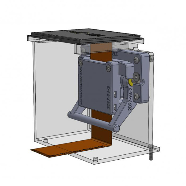
Flexible Test FPC Test Fixture
Flexible PCBs, also known as flex circuits, have revolutionized the landscape of electronic device design and manufacturing. Their use extends far beyond the conventional rigid PCBs, offering unparalleled versatility and adaptability to meet the evolving demands of modern technology.
Flexible PCBs and Their Applications
One prominent area where flexible PCBs excel is in the realm of wearable technology. From fitness trackers to smart garments, these PCBs enable the seamless integration of electronic components into clothing and accessories, providing users with unobtrusive yet powerful devices that enhance their daily lives.
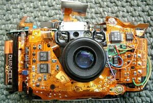
A Flexible PCB Assembly
Moreover, the automotive industry has embraced flexible PCBs for their ability to withstand the harsh conditions encountered in vehicular environments. In automotive applications, where space is at a premium and vibrations are a constant challenge, flexible PCBs offer a reliable solution. They can be custom-designed to fit into tight spaces within the vehicle’s interior or engine compartment, ensuring optimal performance without compromising on durability or functionality. Additionally, flexible PCBs play a crucial role in advancing the development of autonomous driving systems, where complex sensor arrays and communication networks require robust yet flexible electronic interconnects.
Another compelling use case for flexible PCBs lies in the realm of consumer electronics, particularly in the burgeoning market for foldable devices. With consumers demanding increasingly innovative form factors in their smartphones and tablets, manufacturers are turning to flexible PCBs to enable the seamless folding and unfolding of these devices. Whether it’s a foldable smartphone that transforms into a tablet or a compact laptop with a flexible display, the use of flexible PCBs enables engineers to push the boundaries of design and deliver products that captivate consumers’ imaginations.
Furthermore, flexible PCBs find extensive applications in aerospace and defense systems, where reliability and performance are paramount. Whether deployed in satellites orbiting the Earth or embedded within military aircraft, these PCBs must withstand extreme temperatures, vibrations, and radiation exposure while maintaining critical functionality. The inherent flexibility of these PCBs allows them to conform to the contours of the spacecraft or aircraft, optimizing space utilization and ensuring robust electrical connections in the face of dynamic environmental conditions.
In addition to their technological prowess, flexible PCBs offer significant advantages from a manufacturing standpoint. Traditional rigid PCBs often require complex assembly processes involving multiple layers and interconnects, whereas flexible PCBs can be manufactured using simplified processes, reducing production time and costs. Furthermore, advancements in flexible PCB manufacturing techniques, such as roll-to-roll processing and additive manufacturing, have further streamlined the production process, enabling mass customization and rapid prototyping. As a result, flexible PCBs have become not only a staple of cutting-edge electronic devices but also a driving force behind the continued innovation and advancement of technology across industries.
Testing Methods for Flexible PCBs
Testing and inspection are crucial steps in ensuring the reliability and functionality of flexible PCBs across various industries. Several common methods are employed to detect defects, ensure electrical integrity, and validate performance:
Testing and inspection are crucial steps in ensuring the reliability and functionality of flexible PCBs across various industries. Several common methods are employed to detect defects, ensure electrical integrity, and validate performance:
- Visual Inspection:
- Visual inspection remains one of the simplest yet effective methods for detecting surface defects and anomalies in flexible PCBs. Trained technicians examine the PCBs under magnification to identify issues such as solder bridging, missing components, or physical damage to traces or pads. Automated optical inspection (AOI) systems are also utilized to enhance the speed and accuracy of visual inspection, especially in high-volume production environments.
- Electrical Testing:
- Electrical testing is essential for verifying the integrity of conductive traces, ensuring proper connectivity, and detecting potential shorts or open circuits. Various techniques such as continuity testing, insulation resistance testing, and netlist testing are employed to assess the electrical performance of flexible PCBs. In-circuit testing (ICT) and flying probe testing are commonly used methods for comprehensive electrical testing, where test probes make contact with specific points on the PCB to measure resistance, capacitance, and other electrical parameters.
- Impedance Testing:
- Impedance testing is critical for high-speed data transmission applications, where signal integrity is paramount. By measuring the impedance of transmission lines on the flexible PCB, engineers can ensure that signals propagate efficiently without distortion or signal loss. Time-domain reflectometry (TDR) and frequency-domain reflectometry (FDR) are commonly used techniques for impedance testing, allowing engineers to identify impedance mismatches and discontinuities that could degrade signal quality.
- Thermal Testing:
- Thermal testing is conducted to evaluate the thermal performance and reliability of flexible PCBs under operating conditions. Thermal cycling tests, thermal shock tests, and accelerated aging tests simulate the effects of temperature variations and environmental stress on the PCB over time. By subjecting the flexible PCB to extreme temperatures and thermal gradients, engineers can assess its ability to withstand thermal stress without degrading electrical performance or mechanical integrity.
- Mechanical Testing:
- Mechanical testing is essential for assessing the mechanical strength, flexibility, and durability of flexible PCBs. Bend testing, flex testing, and torsion testing simulate the mechanical stresses and strains that the PCB may experience during handling, installation, or operation. By subjecting the flexible PCB to repeated bending and flexing cycles, engineers can evaluate its mechanical robustness and ensure that it meets the required specifications for the intended application.
- Environmental Testing:
- Environmental testing is conducted to assess the performance of flexible PCBs under various environmental conditions, including temperature extremes, humidity, vibration, and shock. Environmental chambers are used to subject the PCBs to controlled environmental conditions, while vibration and shock testers simulate the mechanical stresses encountered during transportation or operation. By subjecting the flexible PCB to rigorous environmental testing, engineers can identify potential weaknesses and design flaws, allowing for improvements to be made to enhance the reliability and longevity of the PCB in real-world applications.
Issues With Standard FFC Connectors
While flexible PCBs offer numerous advantages, they are not immune to failures, and thorough testing is crucial to identify potential issues before they manifest in real-world applications. Here are some common failures encountered during flex PCB testing:
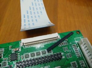
A Failed Connector
- Intermittent Connectivity:
- One of the most challenging issues to diagnose in flexible PCBs is intermittent connectivity, where electrical connections become unstable or unreliable. This can occur due to factors such as insufficient soldering, poor contact between connectors and pads, or damage to the conductive traces caused by repeated bending or flexing. Intermittent connectivity can lead to erratic behavior or complete failure of the device, making it imperative to employ comprehensive electrical testing techniques such as in-circuit testing (ICT) or continuity testing to detect and address such issues.
- Solder Joint Failures:
- Solder joint failures are another common problem encountered during flex PCB testing, particularly in applications where the PCB is subjected to mechanical stress or thermal cycling. Weak or insufficient solder joints can result in open circuits, shorts, or intermittent connections, compromising the reliability and performance of the PCB. Advanced inspection techniques such as X-ray inspection or acoustic microscopy may be employed to detect solder joint defects such as voids, cracks, or incomplete wetting, allowing for timely rework or corrective action to be taken.
- Delamination:
- Delamination, where the layers of the flexible PCB separate or detach from each other, can occur due to factors such as inadequate adhesive bonding, moisture ingress, or thermal cycling. Delamination compromises the structural integrity and electrical performance of the PCB, leading to reliability issues and potential failure of the device. Non-destructive testing methods such as ultrasonic testing or thermal imaging can be used to detect delamination defects and assess the extent of damage, enabling prompt remediation to prevent catastrophic failure.
- Cracking or Fracture:
- Cracking or fracture of the flexible PCB substrate or conductive traces can occur as a result of mechanical stress, excessive bending, or mishandling during assembly or testing. These defects can lead to electrical discontinuities, signal degradation, or complete failure of the PCB. Microscopic inspection techniques such as scanning electron microscopy (SEM) or optical microscopy may be employed to identify and characterize cracks or fractures in the PCB, allowing for corrective measures such as reinforcement or redesign to be implemented.
- Connector Damage:
- Connectors, especially zero insertion force (ZIF) connectors commonly used in flexible PCB assemblies, are susceptible to damage during handling, insertion, or removal of cables or components. Connector damage can result in poor contact, intermittent connectivity, or complete failure of the PCB assembly. Visual inspection, mechanical testing, and electrical testing techniques such as insertion force testing or contact resistance measurement can be used to assess the condition and reliability of connectors, enabling timely replacement or repair to prevent performance degradation or malfunction.
- Environmental Degradation:
- Environmental factors such as moisture, temperature extremes, chemical exposure, and vibration can accelerate the degradation of flexible PCB materials and components, leading to premature failure of the device. Environmental testing, including temperature cycling, humidity testing, and exposure to harsh chemicals, can help identify potential weaknesses and vulnerabilities in the PCB design or materials. By subjecting the flexible PCB to simulated environmental conditions, engineers can assess its long-term reliability and durability, enabling design improvements to be made to enhance performance and mitigate failure risks.
How Flexible Test Line Of Products Address These Issues
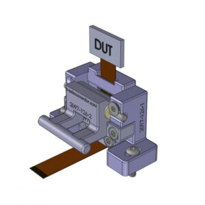
Flexible Test FPC Test Fixture
Flexible Test is renowned for its innovative and reliable flexible PCB test fixtures, offering cutting-edge solutions for the rigorous testing and validation of flexible printed circuit boards. Their leading test fixtures leverage advanced technologies and design methodologies to ensure accurate and efficient testing across various applications and industries.
- Customizable Design:
- One of the key features of Flexible Test’s test fixtures is their customizable design, tailored to meet the specific requirements of each customer’s flexible PCBs. Whether it’s a complex multilayer flex circuit or a simple single-sided design, Flexible Test can engineer a bespoke test fixture that provides optimal electrical contact, mechanical support, and signal integrity during testing. By collaborating closely with customers to understand their unique needs and challenges, Flexible Test delivers tailored solutions that maximize test coverage and minimize setup time, leading to improved throughput and productivity.
- Modular Construction:
- Flexible Test’s test fixtures are built using a modular construction approach, allowing for easy reconfiguration and scalability to accommodate different PCB sizes, shapes, and configurations. This modular design enables quick setup and retooling for different product lines or testing requirements, reducing downtime and maximizing equipment utilization. Additionally, modular test fixtures facilitate future upgrades or modifications, ensuring compatibility with evolving technology trends and product designs.
- High-Frequency Testing:
- For applications requiring high-frequency signal testing, such as RF and microwave circuits, Flexible Test offers specialized test fixtures with enhanced signal integrity and impedance matching capabilities. These high-frequency test fixtures are engineered with precision-machined connectors, controlled impedance transmission lines, and low-loss materials to minimize signal degradation and ensure accurate measurement of critical parameters. By maintaining signal integrity throughout the testing process, Flexible Test’s high-frequency test fixtures enable designers and manufacturers to validate the performance of their flexible PCBs with confidence.
- Elastomeric Contact Systems:
- To ensure reliable electrical contact and minimize test time, Flexible Test utilizes elastomeric connector systems in its test fixtures. These contact systems feature patented elastomeric contact elements that make simultaneous contact with multiple test points on the flexible PCB, reducing the need for manual probing and improving throughput. Additionally, the use of gold-plated elements with low contact resistance ensures consistent and reliable electrical connections, even in challenging test environments. These contacts are field-replaceable as well.
- Comprehensive Testing Capabilities:
- From electrical continuity and functional testing to impedance measurement and thermal cycling, Flexible Test’s test fixtures offer comprehensive testing capabilities to meet the diverse needs of its customers. Whether testing individual components, assembled PCBs, or complete electronic systems, these test fixtures provide the flexibility, accuracy, and reliability required to validate product quality and performance. Additionally, Flexible Test’s test fixtures are compatible with a wide range of test equipment and software platforms, ensuring seamless integration into existing test setups and workflows.
Conclusion
The widespread adoption of flexible PCBs has ushered in a new era of innovation and possibility in electronic device design and manufacturing. As the demand for smaller, lighter, and more versatile electronic products continues to grow, the role of flexible PCBs becomes increasingly indispensable.
With their ability to conform to unique shapes, withstand harsh environments, and enable seamless integration of electronic components, flexible PCBs are driving advancements across industries, from wearable technology and automotive systems to aerospace and consumer electronics. Through meticulous testing, innovative solutions, and a commitment to excellence, Flexible Test remains at the forefront of this revolution, empowering customers to unlock the full potential of flexible PCBs and ushering in a future of limitless possibilities.